Sometimes you get an unclear result when engraving in fast speed, especially by a machine with glass CO2 laser tube, or a machine with servo motor.
On a machine equipped with glass CO2 laser tube, this is because the response delay of the laser subsystem.
- System Schema
When engraving, the movement of the laser head is controlled by the motion subsystem, which responds very fast, and drive the movement immediately after getting the control signal. On the other hand, the laser is controlled by the laser subsystem, which responds relatively very slow. The laser power supply needs some time to be charged to a very high voltage level, usually more than 20,000V, to activate the laser. So, in a slow motion view, you will see the laser head already moves on the way of the scanline, then the laser starts firing, which means the engraved scanline falls behind the expected design position. In dual direction engraving, that will leave an offset between every two adjacent scanlines.
- Engraving Schema
There’s a similar situation happened on machines equipped with servo motors, but with different reasons.
They both can be corrected with the engraving compensation function in EagleWorks or EaglePrint.
Table of Contents
Examine the Offset between Two Adjacent Scanlines
Before applying the engraving compensation, you need to examine the exact offset for a specific engraving speed on your machine.
Offsets are different for different engraving speed
Please do the test for the engraving speed you want to use, or do tests for every single engraving speed you're going to use.
In EagleWorks, draw 20 big letter “I”, shown as below. Set font to Arial, set Width to 100% and Height to 20mm.
- Draw Big Letter I
Set Processing Mode to Scan, set Speed to the specific value you want to test on, set power to a weak level if you plan to test on white papers (which we recommend), set Scan Mode to X_swing (which means dual direction engraving), and set Interval (space between scanlines) to 0.5mm (wider enough to measure the offset easily).
- Set Engraving Parameters
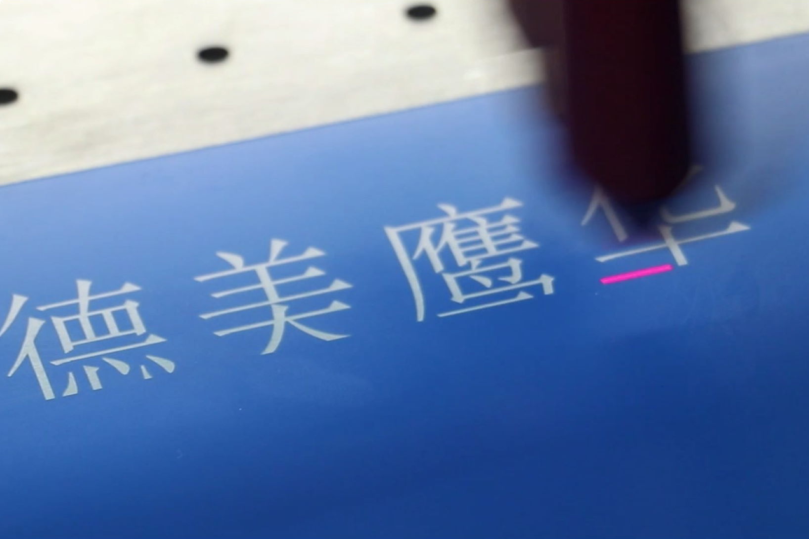
After engraving, you’ll get a result like the picture shown as below. Please measure the offset between two adjacent scanlines, which is two times of the engraving compensation we can set in software to fix this issue.
- Engraving Offset Schema
Eliminate Offsets by Engraving Compensation
After get the offset of a specific engraving speed, you can set the engraving compensation in EagleWorks to fix this issue.
In EagleWorks, click on Config->System Setting menu item, you’ll see the dialog shown as below. Enable Scanning(Reverse compensation) option, click on Add… button, set Speed to the value you had the test on, and set Reverse to half of the offset you got.
- Set Engraving Compensation
Do a test to confirm that you can get a perfect engraving result. Otherwise, you can adjust the compensation value again and again, until you’re satisfied with the result.
It’s actually a nice and helpful piece of information. I am happy that you shared this helpful information with us.
Please keep us up to date like this. Thanks for sharing.


It’s actually a nice and helpful piece of information. I am happy that you shared this helpful information with us.
Please keep us up to date like this. Thanks for sharing.